The onshore cables trench will be approximately 13m deep and 45m wide with an approximate distance of 1m between the two HVDC cables if both cables are within a single trench Drawing NCGEN-NCT-Z-XE-0003-01. 300 power cable concrete cover crossing to instrument.

Concrete Cable Trench Isometric Pdf
The remainder of the trench is backfilled with soil and the area is repaved.

. Place pipes at the edge of trench. 2all dimensions in mm. Cost to be incidental to sewer installation tongue and groove cross section exaggerated bell and spigot cross section exaggerated dry trench wet trench dry trench wet trench revised 022714 by nw jcitydwgcivil 3d drawingsdtlcity sddstrench section detailpdf trench section typical scale 1 1.
4218 Outdoor type cables must be screened and the type of cable must be selected from ElectraNets Standard Drawing. Cable trench type 1 cable trench type 2 cable trench type 3 cable trench type 4 cable trench type 5 polyethylene cable protection strip buried services warning tape peat. A major Kansas power company required Trenwa cable trench that was H20 drive over rated to contain their cablesThey wanted a better way to organize the cables and to maximize the useable space within the cable trench.
2- for cable route marker refer to dwg. Mon 07092018 - 0452. Drawings as per Section 413.
The size length and intervals of the support to be as per the specification. K Substation Standards Switch Operating and Equipment Platforms Electrical Design and Details 20. 4217 Indoor type cables must be not screened and the type of cable must be selected from ElectraNets Standard Drawing.
G Substation Standards Pipe-Bus Grounding Plan 18. Lifting hook shall be provided at every tenth 2. The winch provides smooth and controlled pulling of the cables through the trench.
Electrical Cable Trench Design Detail. If backfill is more than 24 all piping must be SDR 35 or equivalent. Drawing number layout dwg t-layout no.
End View Finished 2 mound for drainage controlGrade 6 maximum cover to cap 9 to 24 backfill cover. 70 PRECASTED POURED-IN-PLACE TRENCH DRAWINGS 20 PURPOSE. 19022020 1712221 171221 - 36 jmcd nm derrinlough wind farm co.
If the trench is rocky placing a layer of clean sand into the trench will help prevent sharp rocks from deforming the MicroDuct over time. A cross-section of the trench is to be shown showing the relative location of the utilities to each other. End of trench ¾ PVC pipe placed every 10 to be used as depth markers and to verify that the bottom of the trench is level.
Offaly planning and environmental. The drawing above shows a cross section of the cable trench. Cable Trench with Underground Devices Cable Management System Requirement.
2001 Amp to 4000 amp services. This cable tray support system drawing has Isometric view and cross-sectional view. Highways Department Created Date.
Cable rating maximum allowable load current is. D Substation Standards Lighting Fixture Pole and Bracket Mounting 19. This standard provides information for construction of Cable Trench.
Ips-d-el-208 ips-d-el-210 1 notes cable trench cable trench for unpaved area typ. When laying a cable into an open trench there are 8 key components within the typical equipment layout used excluding the trench and the cable. Trench length.
Tee trench for all sections. Bottom of the trench. Earth conductor eØ l 50x50x6 clea of lifting hook typ cable trench cover trench width side wall of trench rcc wall l 50x50x6 of precast cover 50x6 flat to be welded drg.
1this drawing is indicative only and is subject to change at the detailed design stage. F Substation Standards Cable Trench Grounding 17. Trenwa later introduced additional trench designs including the One Piece trench Road Crossing trench and XL trench.
If the route requires a turn make several gradual cuts and if possible undercut the corners so the MicroDuct bend radius is not exceeded and it transitions with a natural bend. All steel structure shall be painted a suitable primer before of caeies. Standard Drawing drainage cable trench and duct details SD542 Author.
Install cable tray support using a pre-fabricated flange or GI channel. The conduits are encased in a low strength concrete. Cable trench details chk revisions not to scale date figure 5.
Figure 4-4 shows a typical thermal model of the heat losses and thermal resistances. If the cables and duct are installed in joint trenches with other utilities the type of joint trench used is to be indicated on the as-built drawings including the utilities that are placed in the trench. View Cable Trench drawing example pdf from ME MISC at University of Nairobi.
Cable Trench is suitable for the following conditions. 3cables may be installed by cable plough for. Typical cable trench details this drawing is the properiy of avangrid renewables and is loaned upon condition that it is not to be copied or reproduced in whole or in part or used for furnishing information to any person without the wriiten consent of.
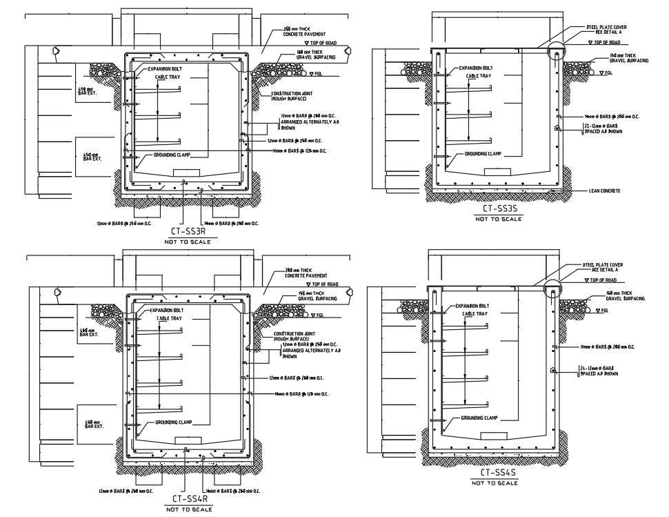
Sukirtianek2 Autocad drawing of Electrical Cable Trench Details showing construction detail through a detailed section. CABLE TRENCH SKETCHES 12 m 01 m 01 m 015 m 025 m min 01 m 075 m min 15 m max 01 m 075 m min15 m max 015. Back fill cable route marker note 2 bottom of trench asphalt paving concrete or cable trench for paved area power and control cable trench instrument cable trench min.
Following are the steps to be done for laying cables on wall mounted cable tray. 2016 environmental statement not to scale 03163d2304-02 na na cable trench of underground cross section figure 215 wind farm corlacky hill notes. 4219 Cables for outdoor application must be either PVC or XLPE insulated according.
For a two-trench design there will be a separation of approximately 3m between the two trenches and 7m between the two cables Figure 41. For this type of cable the electric cables are installed within a steel pipe and a communication cable is installed in a plastic conduit in the same trench. Cable Winch the cable winch is situated at the end of cable trench and is designed to be simple and robust.
Below drawing shows how to install cable tray and its support system. This installation is for underground services from 2001 amps to 4000 amps. BENEFITS OF USING TRENCH ECONOMY - Trenwa trenches are often more economical than poured-in-place trench with its expensive forming costs or duct banks with their costly cable pulling.
The cable component materials and the surrounding environment cause the cable temperature to rise above the surrounding ambient temperature. Details of Cable Trench and Duct Crossing Author.

Jensen Precast Electric Utility Structures Trenches
Cable Trench Drawing Pdf Nature

Cable Trench Section Drawing Pdf

Electrical Cable Trench Design Detail Autocad Dwg Plan N Design

Cable Trench Drawing Pdf Nature

Dwg Cable Trench 850x800 Pdf Pdf Autodesk Computer File

Jensen Precast Electric Utility Structures Trenches
2d Autocad Dwg Drawing File Has The Foundation Details Of Cable Trench Download The Dwg File Cadbull
0 comments
Post a Comment